How to Build Eclíck
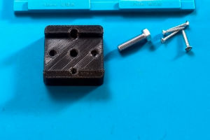
Step 1
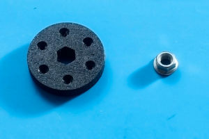
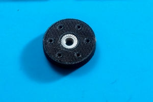
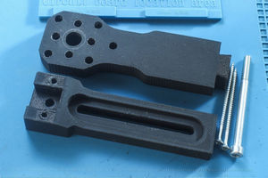
3D Parts: Part-01
Insert the 3/8-16 flanged nut in Part-01 as shown.
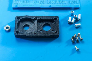
Step 2
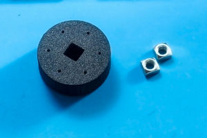
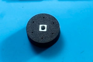
3D Parts: Part-02
Insert the two 8mm square nuts i Part-02.
Step 3
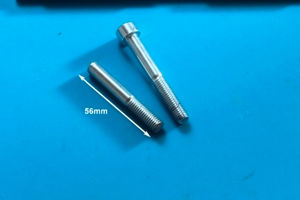
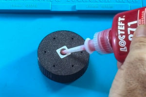
3D Parts: Part-02
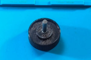
Cut the M8x70mm Allen bolt to 56mm to form the shaft. Apply permanent thread locker to the square nuts in Part-02, then thread the shaft into place.
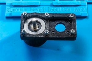
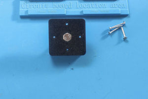
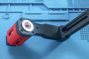
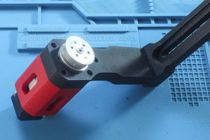
Step 4
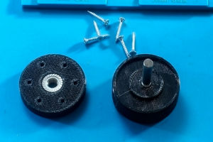
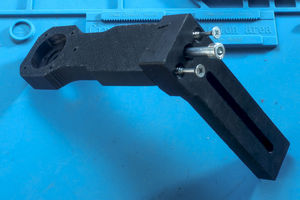
3D Parts: Part-01, Part-02
Attach Part-01 to Part-02 using M3.5x25mm thread-forming (or drywall) screws. Insert the AXK3047 thrust bearing as shown in the photo.
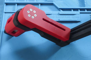
Step 5
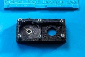
3D Parts: Part-03
Insert the ball bearing and attach the M5x15mm coupling nuts with M5x14 flat head screws as shown. M5x12 flat head screws will also work.
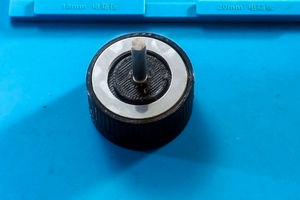
Step 6
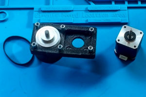
3D Parts: Part-01, Part-02, Part-03
Assemble the parts by guiding the shaft through the ball bearing, as shown in the photo. Place the AXK3047 thrust bearing and slide the 60-tooth GT2 pulley onto the shaft and secure it with the set screws. Attach the 20-tooth GT2 pulley to the stepper motor. Complete the assembly as illustrated in the photo.
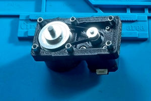
Step 7
3D Parts: Part-04
Attach Part-04 to the assembly using M5x20mm flat head screws.
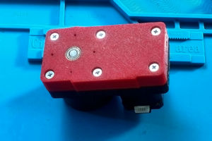
Step 8
3D Parts: Part-05
Insert the M8x30mm hex screw in Part-05 as shown.
Step 9
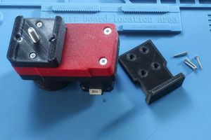
3D Parts: Part-05, Part-11
Attach Part-05 to the assembly using M3.5x25mm thread-forming or drywall screws. Attach Part-11 using M3.5x20mm thread-forming or drywall screws.
Step 10
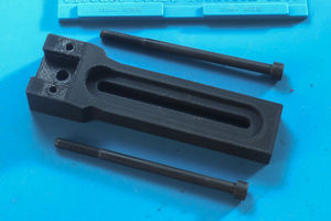
3D Parts: Part-06
Insert the two M8x130mm Allen bolts into Part-06 as shown.
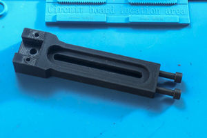
Step 11
3D Parts:Part-06, Part-07
Connect Part-06 and Part-07 and insert the M8x100mm allen bolt and the two M5x90mm self tapping or drywall screws as shown.
Step 12
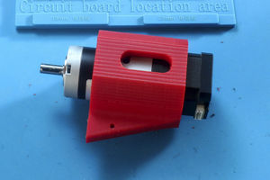
3D Parts: Part-08
Insert the motor through Part-08 and connect to Part-07 using four M4x12mm flat head screws.
Connect Part-07 and Part-08 using five M3.5x25mm thread-forming (or drywall) screws.
Step 13
3D Parts: Part-10
Insert motor shaft throughr Part-10 and then place AXK2542 thrust bearing as shown in photo.
Dril and tap six M4 screw holes to match the holes in Part-09 in the GT2 pulley that has a 3mm keyway.
Place pulley on motor shaft and secure in place with a M3x16mm screw and washer. Use threadlocker to ensure the screw does not come loose.
Step 14
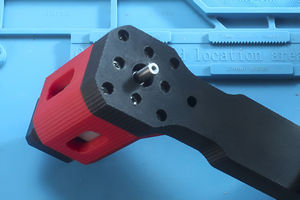
3D Parts: Part-09
Attach Part-09 to the GT2 pulley with six M4x25mm flat head screws